So... I connected my lawn to the internet.
More specifically, I built an internet-based control for the thing that most contributes to the on-going health of my lawn. That is, the sprinklers.
I call this project Irrduino, because at the core of it is an Arduino microcontroller that lets me remotely control the irrigation zones at my house. Irrduino communicates via Ethernet and standard html requests and responses (specifically a REST interface with JSON responses, for you web geeks out there) which means I can control my sprinklers from anywhere on the planet with a web browser and an internet connection, or any smartphone with the same.
Why the heck would I want to do that?
Well, first and foremost, because I can. I wanted to see if I could do it. Beyond that, there are some very practical reasons for wanting to do this, which should be readily understood by anyone who has ever had to do maintenance on sprinklers. They need to be tested regularly, and when you test sprinklers, it’s best to be able to chose exactly where you are standing when the water comes on. So being able to turn them on from my phone is very handy for testing. But that’s not the best part.
The best part, by far, is being across the street at my neighbor’s house and seeing the neighborhood cat preparing to use my lawn as a a toilet, pulling out my phone, pushing a button and watching the feline fur fly.
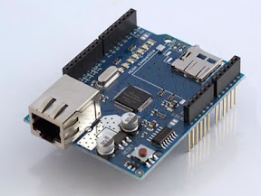
 I started with the Android Accessory Development Kit (ADK) as my Arduino platform. In retrospect, this board is massive overkill for the project, but it’s nice to have a extra headroom just in case. I knew early on that I didn’t want to have the ADK plugged into my phone so I invested in an Ethernet Shield so I could connect it to my home network. After it arrived, I spent about a week trying to figure out why it didn’t work, until I discovered that the shield needs to be plugged into the Arduino ISCP header pins, which don’t exist, as such, on the ADK. Luckily those connections can be made separately, and once I figured that out, it was off to the races with a teeny, tiny little web server.
Next, I needed a way to control the higher voltage circuits of the sprinkler value solenoids. Sprinkler systems typically run at 24 volts and somewhere between 700 and 1000 milliamps. After a bit of research on the topic, I figured out the electronic component I needed to control these higher power circuits was called a relay. Being rather new to electronics engineering, I settled on something that was prebuilt and designed to work with Arduino. For that reason, I bought a few of Seeed Studio’s Relay Shields, waited for them to show up, then hooked them up and once again spent another a week trying to figure out why they didn’t work.
Turns out the Relay Shields are a bit power hungry. Running them off the 5-ish volts of USB power that easily runs the ADK and the Ethernet Shield, is not enough to run the Relay Shields. It’s a bit annoying, but easily solved with 9 volt wall adapter plug connected to the ADK, and then connecting the Vin power pin and neighboring ground to a power bus connected to the power inputs for the Relay Shields.
 After bringing all this hardware together, I started wiring it all up and writing the Arduino control software. The first task (after figuring out that the the shields needed 9 volts of power) was connecting the control wires to the Relay Shields signal inputs. After a quite a bit of experimentation, I settled on using standard Arduino pins 2 though 9 for controlling the first two shields, and pins 11 and 12 for the third shield.
There were a couple of key learnings from the wire-up process:
There are several separate software projects that contribute to the functionality of Irrduino:
The IrrduinoController software presents REST-like interface for client applications like the IrrduinoRemote app, the IrrduinoServer, or anyone with a web browser. The software call for turning on a sprinkler valve drives digital output HIGH, thereby activating a relay, closing a circuit for one of the valve pumps and turning on the water. Once you know which sprinkler zone to activate and the digital pin associated with it, all you need to do is call:
More challenging is receiving and interpreting a REST command to turn on a zone, and running a sprinkler zone for a specified amount of time without blocking the processing thread. Luckily, I had some help and inspiration for interpreting REST commands from Jason Gullickson’s excellent RESTduino project. For the non-blocking timer, the Arduino forums were quite helpful in suggesting setting a end time with the millis() function and running a check function on each loop.
There was a lot of trial and error and rework for the Arduino code, and I’m already planning a major refactor to make extension of the Irrduino code. I’ll let the code speak for itself, with the caveat that it is not particularly elegant but, it works.
As I was working on this project, it became clear to me that the Irrduino system could easily do more than just remotely activate my sprinklers; it could actually run them, full time, and thus allow me to replace my commercial controller with a completely open source, open hardware solution that would give me way more control and flexibility in how I watered my landscape. I could give it a regular schedule to run, and then give it enough smarts to adjust watering based on seasonal timing, predicted weather, actual rain (rain sensor), or do even smarter things like automatic soak-wait-soak scheduling, water budgeting and more.
For Irrduino 2.0, I plan to add timed scheduling, and after that the sky's the limit.
More specifically, I built an internet-based control for the thing that most contributes to the on-going health of my lawn. That is, the sprinklers.
I call this project Irrduino, because at the core of it is an Arduino microcontroller that lets me remotely control the irrigation zones at my house. Irrduino communicates via Ethernet and standard html requests and responses (specifically a REST interface with JSON responses, for you web geeks out there) which means I can control my sprinklers from anywhere on the planet with a web browser and an internet connection, or any smartphone with the same.
Why the heck would I want to do that?
Well, first and foremost, because I can. I wanted to see if I could do it. Beyond that, there are some very practical reasons for wanting to do this, which should be readily understood by anyone who has ever had to do maintenance on sprinklers. They need to be tested regularly, and when you test sprinklers, it’s best to be able to chose exactly where you are standing when the water comes on. So being able to turn them on from my phone is very handy for testing. But that’s not the best part.
The best part, by far, is being across the street at my neighbor’s house and seeing the neighborhood cat preparing to use my lawn as a a toilet, pulling out my phone, pushing a button and watching the feline fur fly.
Hardware

Turns out the Relay Shields are a bit power hungry. Running them off the 5-ish volts of USB power that easily runs the ADK and the Ethernet Shield, is not enough to run the Relay Shields. It’s a bit annoying, but easily solved with 9 volt wall adapter plug connected to the ADK, and then connecting the Vin power pin and neighboring ground to a power bus connected to the power inputs for the Relay Shields.
Wiring

There were a couple of key learnings from the wire-up process:
- Don’t Use Pins 0, 1, 10, 13: These pins receive quite a bit of signalling for other purposes, so don’t try to use these as output controls for the relays. Pin 13 on the ADK, in particular, gets flashed quite a bit when you upload new programs, which I spend a lot of time doing. Once you have a program that you are happy with and don’t need to update, it may be OK to use it.
- NC, NO: What’s that? On the Seeed Studios Relay shield the big, green screw terminals are labeled NC#, COM#, NO#. This stands for Normally Open (NO), common wire (COM) and Normally Closed (NC). For use with a sprinkler system, the control circuits are usually disconnected (Open) and only connected when the sprinkler valves are open, so I used the NO terminals to connect the sprinkler valve circuits.
Software
There are several separate software projects that contribute to the functionality of Irrduino:
- IrrduinoController - This software runs on the ADK / Arduino microcontroller and is the core of the Irrduino project. It runs a small web server, handles the http REST requests, activates and deactivates the relays to turn the sprinkler values on and off.
- IrrduinoRemote - This Android application is what I'm using in the video to activate the IrrduinoController. There is not much to this application, because there doesn't need to be. I wrote the original, functional version in about 3 days.
- IrrduinoServer - This Google App Engine server application acts as a reporting backend and alternative controller it was written in Python by my partner in crime on this project, JJ Behrens.
The IrrduinoController software presents REST-like interface for client applications like the IrrduinoRemote app, the IrrduinoServer, or anyone with a web browser. The software call for turning on a sprinkler valve drives digital output HIGH, thereby activating a relay, closing a circuit for one of the valve pumps and turning on the water. Once you know which sprinkler zone to activate and the digital pin associated with it, all you need to do is call:
// turn on selected zone
digitalWrite(pin, HIGH);
More challenging is receiving and interpreting a REST command to turn on a zone, and running a sprinkler zone for a specified amount of time without blocking the processing thread. Luckily, I had some help and inspiration for interpreting REST commands from Jason Gullickson’s excellent RESTduino project. For the non-blocking timer, the Arduino forums were quite helpful in suggesting setting a end time with the millis() function and running a check function on each loop.
There was a lot of trial and error and rework for the Arduino code, and I’m already planning a major refactor to make extension of the Irrduino code. I’ll let the code speak for itself, with the caveat that it is not particularly elegant but, it works.
Irrduino 2.0
As I was working on this project, it became clear to me that the Irrduino system could easily do more than just remotely activate my sprinklers; it could actually run them, full time, and thus allow me to replace my commercial controller with a completely open source, open hardware solution that would give me way more control and flexibility in how I watered my landscape. I could give it a regular schedule to run, and then give it enough smarts to adjust watering based on seasonal timing, predicted weather, actual rain (rain sensor), or do even smarter things like automatic soak-wait-soak scheduling, water budgeting and more.
For Irrduino 2.0, I plan to add timed scheduling, and after that the sky's the limit.